Inside a PCMCIA WLAN card.
My current [05/09/2002] project involves the use of a Direct-Sequence spread spectrum radio link. After much um-ing and ah-ing, I've decided to use part of a wireless LAN chipset to do a lot of the hard work for me.
Having looked at Farnell, RS, and other distributors, and having talked to Intersil (formerly Harris) who make the WLAN chipset that I want (PRISM2), I discovered that the easiest way of getting my hands on the chips I wanted quickly was to buy a WLAN card.
(The MAC is about 20 pounds, the IQ modem about 15, and a WLAN card with them in about 50).
Anyhow, here it is, a Cisco AIR-PCM340 (Aironet 340 series).

Its WiFi certified, 2.4GHz DSSS (that's IEEE802.11b), supports data rates of 11, 5.5, 2 and 1Mbps, and doesn't do any WEP at all (there are other cards in the 340 series which do... I'd speculate that a firmware upload into the MAC chip would have it singing WEP in no time...).
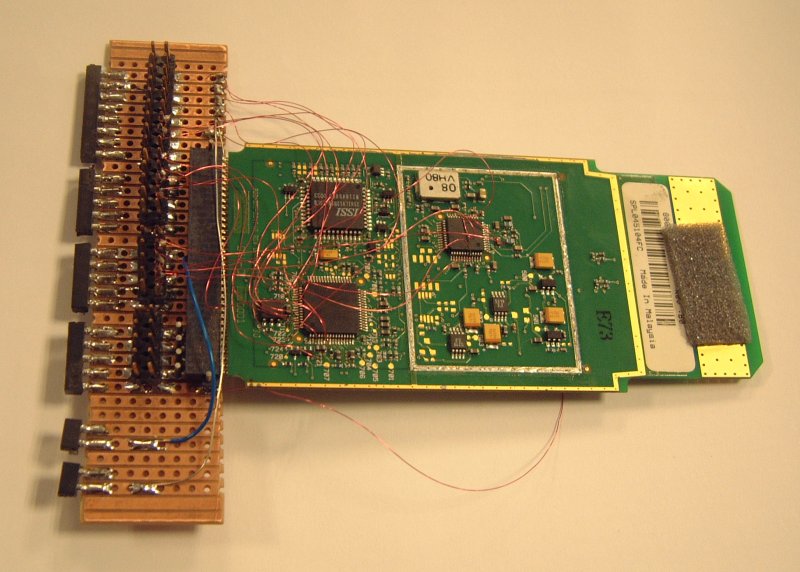
Into the guts of the thing: (click on a picture for a big uncommented version)

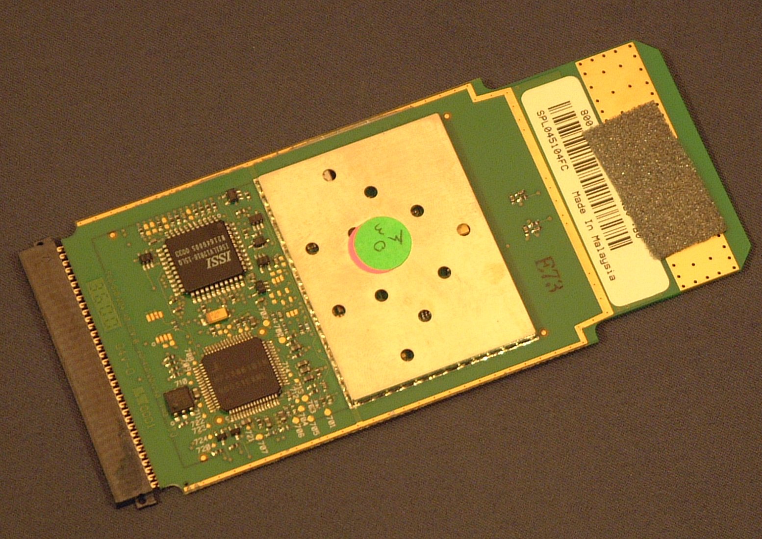
On the MAC side:
- Aironet MAC chip, labelled 608-004808-1
- AMD AM29LV002BB - 256KB (2Megabit x 8) Flash ram (bootsector?)
- 44MHz crystal (BBP clock)
- Dallas/Maxim DS1073 fixed frequency oscillator
- SAWTEK 855653 - 374MHz (IF) filter
- Antenna diversity switch
- Screened things...
- Intersil HFA3861B Baseband Processor
- ISSI IS61LV12B16-15LQ - 128k x 16 Asynchronous SRAM (packet buffer?)
- Dallas/Maxim DS2401 - "Silicon serial number" (forms part of the MAC address?)
- Another screened area...
And under that screening:
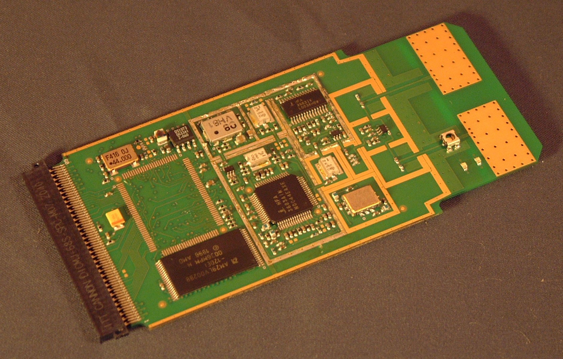
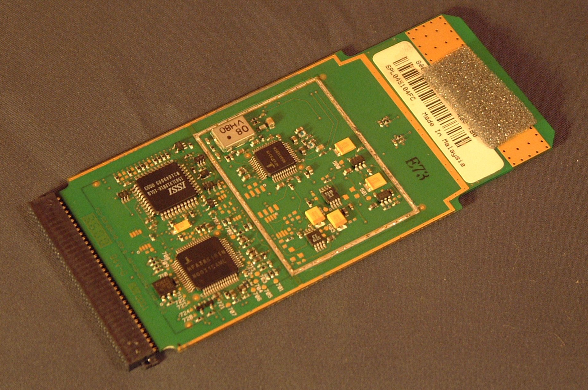
More on the MAC side(MAC chip now removed):
- Intersil HFA3683A - RF <--> IF convertor
- Intersil HFA3983 - TX Power amplifier
- GaAs FET Transmit/receive switch
- 2.4GHz VCO (the HFA3683 completes a PLL)
- 3 filters (white oblongs), presumably TX, RX, and IF
- Intersil HFA3783 - IQ modem
- An IF VCO, I think
Here is the state it is in just before its assimilation into the collective (jpeg image 89kB (that's 87kiB for the computery people who think a kilobyte is 1024 bytes)).
What I've learned more recently(24/09/2002)
The DS1073 IC is ticking away at 48kHz (but the MAC is removed, so its possible that the MAC software could re-program the frequency on the fly; but I don't think it does). This looks like a sleep timer or something. I'm not particularly interested in it at the moment.
The 44MHz crystal is also clocking the HFA3783 and 3683 (IQ MODEM and RF/IF convertor IC's), hence the whole system is running from a common clock.
The "3 filters (white oblongs)" I referred to are dielectric filters. I disagree with my previous supposition that these are IF, RX and TX. The SAWTEK filter is the IF filter. I believe these are LO, RX and TX filters, at much higher frequency. RX and TX filters will be across the 2.4GHz band, the LO filter slightly offset (by the IF frequency). I don't think the bandwidth of these filters is particularly tight, I think they're more for filtering harmonics, so it might be that all three are identical.
The two VCO's are used in conjunction with the HFA 3683 and ~3783 chips, which contain the remainder of a PLL. The VCO's frequency is divided and compared with a reference obtained by dividing the 44MHz (crystal) clock. An error signal is produced which is (externally filtered and) used to drive the control voltage of the VCO to correct any frequency error.
Abbreviations:
MAC - Medium Access Controller
BBP - Baseband processor
DSSS - Direct Sequence Spread Spectrum
SAW - Surface Accoustic Wave
VCO - Voltage Controlled Oscillator
PLL - Phase Locked Loop
I've kind of ground to a halt with this page now. There's more knowledge in my head, but a distinct lack of incentive to write it up. Mail me if you want to know more, an p'raps give me a clue about what in particular you'd like to know more about. Email address below.
Addendum 14/01/2003
How would one increase the output power of one of these cards?
First things first, do you really want to increase the output power?
Increasing the output power of your card will help it transmit a signal to another card, or to an access point which is further away. The problem generally is that the other end of the link needs the same modification. Amplifying the incoming signal aswell generally does not help, as the noise is also amplified.
A better solution is generally to use a directional antenna. This provides additional gain to both transmitted and received signals without increasing the noise significantly.
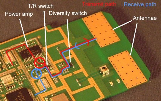
In the diagram below, the transmit path has been illustrated with a red line, and the receive path with a blue line. A number of components are also identified. In transmit mode, the signal from the RF/IF convertor passes through the power amp, and then a switch which connects either the transmit circuit or the receive circuit to the antenna. The last switch is the antenna diversity switch which can select either one of the two internal antennae.
When receiving, the diversity switch toggles to and fro at a rate of 48kHz (that's what the DS1073 IC is for.. (see earlier)). When a significant amount of RF power is detected, the diversity switch stops toggling.
I've added a couple of circles to the diagram to show possible locations for an additional power amp in the transmit path, and an LNA in the receive path (there's the possibility of trying to make the reciever more sensitive this way if the onboard LNA is not particularly sensitive.) I'm not going to get into the design of LNA's and power amps at 2.4GHz. If you don't know how to set out on this task, there's a lot to learn. I think the power output of the card as stands is 100mW (20dBm), so you're probably going to want about a quarter watt amplifier. I don't think any of the modular amplifiers can push out that much power.
However, as I mentioned earlier, my choice would be to use a directional antenna. I'm not even sure there's enough power supply available on the card to drive further power amps, and there's not a lot of room left really.
The use of diversity means that a directional antenna can be used for one connection, and the on-board antenna for the other, so you still stand a chance of communicating with wlan devices which are outside the directional antenna's main lobe. My choice would be to replace the test connector located near the lower antenna with a surface mount MMCX connector. Some additional strengthening with araldite would be required, as these connectors have a habit of ripping the pads to which they are soldered from the circuit board. With an appropriate hole made in the housing, an MMCX plug can be mated with the board when the card has been inserted into a pcmcia slot.
I'm going to write a little more on this once I've researched a few things.